We do have a couple of app notes and a video that can help you with the 1586 automated calibration process. I think those are pretty beneficial. You can find those on the website. If you have any questions about those, we’d be happy to talk to you about them.
Back to Top of Page ↑
In summary, dry-blocks are a great option to use in a lot of situations. They are very versatile, light-weight, very portable and very quick to change the temperature in most cases. We do need to make sure we consider the sources of error that are associated with that. On-board references are a great way to combine instruments, so we’re not packing around an extra meter and a probe in addition to the dry well, and be sure to let any of us at Transcat or here at Fluke know how we can help with your specific application. Both companies have a lot of resources and great people who can help you resolve your calibration needs. With that, I think I’ll turn the time over to Nicole and she can wrap up, and then we’ll do some questions and answers.
Sure. Could you advance one slide for me? Obviously, that concludes our presentation portion of the webinar. Before we go on to answer any questions that were submitted, there is a limited time offer that you guys should look into and we will forward the details in a follow-up email, but there is an offer going on now that when you purchase a metrology well and an additional probe, or case, you will get a free additional temperature probe, and that’s worth over a thousand dollars. You might want to look into taking advantage of that. Again, we’ll send details later.
Back to Top of Page ↑
1. How often do I need to calibrate RTD?
That’s a great question, “How often should I calibrate an RTD?” It really comes down to a matter or risk. If you’re out using an RTD in an environment where at a tolerance condition or failure could be a real problem for you, then you might want to consider reducing calibration interval or at least doing an interim check more often. If a probe is handled properly and it’s not subject to a really high range of temperatures at its maximum, it’s likely that it doesn’t get a change a whole lot, but there is absolutely no way for anybody to guarantee that it won’t. We always have to consider that there is some level of risk associated with that. Lower temperature ranges and handling them properly definitely helps with that.
We would recommend that you evaluate your situation specifically to determine how often you should calibrate it. Another tool you can use to determine that is to evaluate, maybe shorten the calibration interval for a couple of times and see how the probe is behaving in the environment that it’s used in. If it seems to be that it’s not moving around much, it’s not drifting and it’s pretty stable, then you could consider lengthening that cal interval. Unfortunately, there is not one solid answer for that question, but if you’d like to discuss it more, you’re more than welcome to give me a call and we can talk about it some more.
Back to All Q&As ↑
2. Is the reference probe a SPRT/NIST calibrated probe or can I use any RTD obtained coefficients using the dry-block, and then utilize it as my reference and proceed to calibrate the rest?
Yes, good question. You can use any RTD or SPRT that you’d like to be your reference. If you remember the slide about the GUM compliant uncertainty analysis, we would have an uncertainty associated with that reference probe. If it’s an SPRT that was calibrated in fixed points, the uncertainty of the reference contribution would be quite a bit smaller than if it’s an RTD that was maybe calibrated by a comparison. Most of the time, the probes that we see used in references for dry-block calibrators are typically just an RTD, but in some cases a metal sheath SPRT is used, as well, on some of the deeper probes. I hope that helps to answer that question, but it would be okay to use either.
Back to All Q&As ↑
3. Is there an immersion equation for thermocouples?
Thermocouples are a little bit different animal. We probably won’t be able to get into detail about this. We do have some webinar series around thermocouple calibration but a good rule of thumb if you’re doing comparison measurement is to put the junction of the thermocouple, or the tip of it, in the center of the sensor of whatever you’re comparing it to. You might have to draw the thermocouple up off the bottom of the dry well maybe a half an inch if your reference probe has an inch-long sensor in it. It’s good to try to align the center of those junctions, but thermocouples are a completely different animal. The voltage is typically generated in the gradient zone of a thermocouple. That can be a little bit of a challenge, but it’s a good rule of thumb, as we illustrated with RTDs to insert them fully, and then maybe draw them off the bottom a small amount.
Back to All Q&As ↑
4. Is the proportional band a reference to proportional parts?
I’m not sure I understand that question but I’ll try to answer it the best I can. A proportional band is designed to dictate the behavior of the controller in a dry well on how it behaves if the temperature starts to drift a little. If it starts to cool off or heat up, the controller wants to take over and adjust for that. The proportional band setting will determine how the dry well behaves when it reacts to that, more like a response, if you will, from the dry well, is what the proportional band is. As I’ve mentioned before, on any good calibration report, it should tell you what the proportional band was when the unit was calibrated. It’s always best practice if you don’t do a bunch of testing to figure it out. It’s best practice to set it at that value, unless you’re doing something special.
Back to All Q&As ↑
5. What are your thoughts on movable jaws for dry-block calibrators?
I’m not quite sure I know exactly, that might be a removable insert question but I’m not quite sure what it meant by that. If we could get a little more clarification, but many of the dry wells have inserts that you can take in and out, and that’s certainly something that we feel acceptable.
The person that posed that question, if you want to send me a follow-up email, then we can facilitate getting you an answer to that one. My contact information is on the last slide, if we advance to that. Do you want to advance to that part? We’ll also send it in the follow-up email. Next one.
I did see a follow up about the movable jaw. “Movable jaw is spring-loaded for different diameter probes instead of using inserts of various diameter holes.”
I think I’ve heard of those, but I have never really laid eyes on one. I think if you think about that concept, I think the idea is that as I put probes in an out of this instrument that it will accommodate different sizes. The concern with it is how much of an air gap do I have after I put the probe in the device. If you see that there is a substantial air gap around the probe, there are going to be some uncertainties associated with that and how far away we are from the ambient environment will have a role in it. It’s a little bit difficult for us know. A test with a calibrated probe versus maybe a non-calibrated probe would be one way you could try to figure that out, but I don’t have a lot of experience with those spring-loaded inserts.
Back to All Q&As ↑
6. What’s the difference in accuracy in a dry-block versus an oil bath?
It can be pretty drastic. The reason being is the uniformities, instabilities and the errors that we talked about in the slide presentation today are generally a lot smaller in an oil bath. You could increase the performance of the calibration system by quite a bit by using an oil bath. The challenges with oil baths are that the trade-offs are that they don’t move temperature very quickly at all. They are typically fairly slow to change temperature. The range is fairly limited with fluids. We can cover -200 up to about 550 C with fluids but it takes different types of fluids to do that, where in a dry-block calibrator it’s pretty for us to move quickly and cover a broader range of temperatures. There is pluses and minuses to both situations, but typically speaking, baths would perform better in terms of keeping those uncertainties as low as possible.
Back to All Q&As ↑
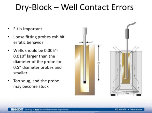
7. Does the probe need to be bottom out or can there be an air gap?
It’s a good question. It’s okay for us to have an air gap at the bottom of a well, but as we talked about in the slides with immersion depth, you want to try to follow that fifteen times the diameter, plus the sensor length rule to help us to accommodate the stem conduction problems that we might get. There is no need for it to be resting at the bottom. If it doesn’t quite get there, that’s okay. We just want to consider those other sources of errors that we talked about.
Back to All Q&As ↑
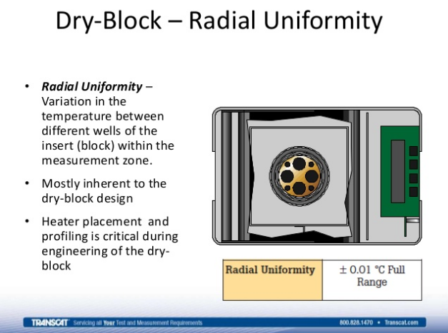
8. On the slide for dry-block and two probes they looked like they were in the same hole. If so, wouldn’t the tips give off extra heat to each other?
I think he might be talking about where we were doing the calibration example and those two probes would’ve been in separate holes within the dry well. We have one illustration there we could see there were about eight holes in the top of a dry well, and we were talking about considering the hole to hole gradient, or the radial gradient specifications. If you have two probes that are in a well and they are touching, probes typically don’t provide a whole lot of self-heating. There is a very, very small amount and at the highest levels of temperature metrology, we can measure that parameter, but when we put probes in a hole next to each other I don’t typically see them heating each other up. A bigger problem is when we put two probes in one hole is that we have a lot of air gap around them and that creates uncertainty in the measurement, much more than any sort of self-heating or heating of one another would.
Back to All Q&As ↑
9. Where did you get the values to populate the table in the calculating uncertainty slide?
It’s a good question. Those values that was an example of an uncertainty budget we use in our lab. Over time, obviously we’ve tried to do our best to improve those where we can. Many of them come from spec sheets relating to equipment that we use. Others come from actual experiments and measurements that we make within our lab, but typically speaking, uncertainties come from the specification sheet from the manufacturer when we put those into an uncertainty budget like that. If we feel like we can make an improvement on one of them by doing some testing, we may do that and if there is one in particular you’re interested in or want to talk about that more, you can reach out to us about that.
Back to All Q&As ↑
10. For odd-shaped thermocouples, how would you calibrate a flat surface thermocouple?
That’s a really great question. We run into that quite often. There has been a couple of approaches in dealing with flat shapes or odd shapes in a dry well. I mentioned us being able to manufacture a custom insert. We’ve done a few that act like a bit of a clam shell where you would actually split the insert in two pieces and you would be able to put the probe in place, and then close the clam around it, the two pieces of the insert and then put in the dry well. That’s one option. The other option is to do it in a fluid to alleviate those sorts of problems, but it’s typically going to be a custom insert or go to a fluid.
Back to All Q&As ↑
11. Is it advisable to use the ITS90 table along with the dry-block and RTD own reader with no reference probe?
I think I know what we’re getting at here. The concept would be I have an RTD and a dry-block and measuring the resistance of it, and then pulling it off of a chart of some sort. The concern there is without calibration coefficients for the probe, how do we know what the behavior of the probe is? Unless that table has been generated for that probe specifically. If it’s a generic table, I would use some caution there. I think it’d probably be better off to make sure that whatever table I’m looking at is in relation to that specific probe. If it is, then that’s an acceptable way to do it, using a look-up table, but you’ve got to make sure it’s the table for that probe because no two probes are the same.
Back to All Q&As ↑
12. What if you have multiple thermocouples in one dry well? Would you suggest keeping them on in the middle or keep individually?
Yes. That’s a good question. A lot of times we see with thermocouples, people will bundle them together and put them all in one hole. I’ve seen done both ways. Sometimes they can be really small in diameter. If you don’t have an insert with that many small holes in it, it’s advisable to put them all together in one hole. If it’s possible to stick a fourth one in there to tighten up the fit a little bit, even though you’re not measuring it, it might be advisable to try to take off some of the air gap associated with that. Then making sure that they are fully immersed that we get them several inches into the dry well. That would be a critical component, but it is pretty common for people to do that with thermocouples and I think it tends to work well.
One thing you’ve got to remember with thermocouples is the uncertainties of a thermocouple can provide something on the order of a degree, maybe half a degree if you’re around ambient conditions, you’re not asking too much of it. All those uncertainties we were looking at earlier, when you relate them to the capability of a thermocouple, there may be not quite as big of a concern. Just make sure you’re not trying to get a couple of millikelvin out of a thermocouple, and that’ll help.
Back to All Q&As ↑
13. If a calibrated reference RTD is used for comparison, is it necessary to return the dry-block itself for recalibration periodically?
It’s a great question. It doesn’t necessarily need to come back to the manufacturer, unless we feel like there might be something with it. We do want to make sure that it’s stable, so the reference probe, you’d want to look at that at temperature and make sure that it’s not drifting around and it seems to be meeting the specification of the manufacturer put on stability, but when you’re not considering what the temperature display of the dry well says, when you’re relying on a reference probe, there really isn’t a need to send that in routinely, unless you think there is a problem.
I’m just going to put in a plug for Transcat, because we do offer calibration services for dry-blocks and basically all the types of measurement instruments that we sell.
Back to All Q&As ↑
14. What if the probe is an inch-long? Would this work in a dry-block or would a bath be preferred?
Yes, something that short we would definitely prefer to do in a bath. The diameter of that probe could also cause some problems, if it’s really small in diameter that would be helpful, but the challenge is you need to try to put a reference probe at the same depth, if you can, and that likely one-inch is going to have a huge impact on a reference probe. It’s a bad scenario. If the uncertainty of what you’re trying to do is a couple of degrees and you’re within a hundred degrees of ambient, you might be able to stay within that couple of degrees, but it would be advisable to try to do that in a fluid, in a micro-bath or something like that, if you can.
Back to All Q&As ↑
15. Can I perform an RTD reading with a moving portable dry-block being held with your hands perhaps vertically? In other words, with the Fluke’s 9100, will it introduce some sort of error? Some probes cannot be removed and the calibration may have to be performed in hard to reach areas.
I think, if I am understanding the question right, it’s the orientation of the dry-block during that cal process is not critical. If I needed to hold it horizontally or vertically or at an angle that would certainly be okay. With that 9100, we see that used all over the place in factories and tight spaces, hard to reach spaces and it’s certainly okay to do.
Back to All Q&As ↑
16. If the inserts get stuck in the calibrator, is there something I can do to try to remove it?
Good question there. I’ve had plenty of experience back in my days with service in trying to remove the stuck inserts and depending on the situation, they may or may not ever come out of there. You can try a little bit of WD-40, let it soak down between the seam and the insert, but I would certainly recommend that you just do small amounts over a period of time, and then try to use that to break it loose, but it’s possible that it is stuck for good. The problem is if a piece of debris gets between the insert and the block, and then if you pull it up a little bit and it just keeps getting tighter, then it’s kind of gulled and it probably won’t come out. You could always work through us, Transcat, to try to get that repaired. If you don’t need the insert to come out, it’s probably okay if it stays there too.
During the repair, we also offer dry block rentals. If you need a rental during downtime, you can definitely look us up. Give us a call or check us out online. We had a lot of great questions today. That concludes our time today. It’s just about three o’clock. Again, if you have further questions or would like to find out more about our products or service offerings, you can contact us at 800-800-5001. On the web, it’s Transcat.com, or you can email me directly at [email protected]. Thank you everyone for joining us today and thank you, Kurt. We hope you got something out of today’s presentation and that you continue to join us for future Transcat e-learning webinars.
Thanks everyone.
Back to All Q&As ↑